GL1800Riders Forums banner

Electrical connection Low Beam Cutout Harness

18K views 117 replies 14 participants last post by  Waldo  
#1 ·
I tried to install this wire harness from electrical connection, but the installation instruction is apparently not for my goldwing.

I have a '07 NAV/AIRBAG.

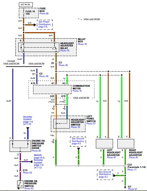
The instruction says I should connect the supplied 't-tap to the brown wire on the "HEAD LIGHT ADJ" relay, but as you can se on the drawing below I have no wire in this socket.

Which one should choose instead?

Poul
 

Attachments

#5 ·
The Headlight adjust relay is over to the left (sitting on the bike) on the same bank of relays, you are finding the brown wire that goes into this relay. You are dealing with two of the OEM relays to do this install.

On the US models Headlight Adjuster relay, there are a few that are brown and red striped wires, but only one that is solid brown, although it has some hoops of silver on it (all the wires seem to have this this.

You plug the OEM Headlight Lo relay into the socket relay on the EC unit. The EC wires plug into the empty Headlight LO relay socket, that you just pulled the relay out of. The brown wire connects over, as the trigger, to the Headlight Adjuster adjust brown wire.

You can tuck the EC relay socket and relay below the relay bank before you screw the bank back down.


Hope this helps.
 
#6 ·
The Headlight adjust relay is over to the left (sitting on the bike) on the same bank of relays, you are finding the brown wire that goes into this relay. You are dealing with two of the OEM relays to do this install.

On the US models Headlight Adjuster relay, there are a few that are brown and red striped wires, but only one that is solid brown, although it has some hoops of silver on it (all the wires seem to have this this.

You plug the OEM Headlight Lo relay into the socket relay on the EC unit. The EC wires plug into the empty Headlight LO relay socket, that you just pulled the relay out of. The brown wire connects over, as the trigger, to the Headlight Adjuster adjust brown wire.

You can tuck the EC relay socket and relay below the relay bank before you screw the bank back down.


Hope this helps.
Thanks ChrisE, if you look at the picture I attached the socket to the left has two brown wires both with a red stripe, the next to the right is a solid brown wire. Is it this wire I should use?

Poul
 
#9 ·
Yes, you got it..
I have tried to connect the brown wire to the brown wire on the “HEAD LIGHT ADJ”, but still no light either with the ignition On or the bike is running.


Now I tried to measure the wires and it seems that there is soldered a diode on the brown wire and the power goes from the connector


Bottom line still no light.:!:

Poul
 
#10 ·
I really can't help with the technical aspect of the installation, but I have the EC cutout harness on my 2003 wing, and it works as it should. I do remember that I had to really look closely to find the correct wire to clamp the connector into--it was not quite what/where I first thought it should go. Sorry, I can't be more precise, but my CRS is beginning to advance to CRAFT.
 
#11 ·
Try this

On the Headlight adjust relay measure all the wires with a meter without the engine running, then do it with the engine running you need the wire that gives 12V when running tap that one, make sure all your relays are in place when you test this
 
#17 ·
I'm a little confused, when i connect the brown wire on the EC harnes to the brown wire on the HEAD LIGHT ADJ relay nothing i happining. There is no light on the bike with the ignition in the ON position, and also no light when the bike is running.

But if I push the head light adjust switch with the bike running the light came on. Is this normal with this wire harness? :shrug:

Poul
 
#18 ·
You pig tailed off the wrong wire.....by the sounds of it.
 
#20 ·
Did you plug the OEM Headlight LO relay, that you pulled out, into the the EC relay socket?
 
#22 ·
Hard to tell in the pic, the the wire colors appear correct. My ETM shows the same wire colors back to 2001 as to my 2006 diagram....and we have tested this on a 2008 bike.

I see a meter in the photo. Lets do this;

1. Set it to 'dc volts'.
2. Connect red from the meter to battery hot.
3. Connect black from the meter to the brown wire with NO red on it from the Headlight Adjust Relay.
4. You should have nothing. Start bike....once the oil pressure light goes off you should have 12 volts.
5. If you get voltage, it's one of 2 things;
a. you either don't have a good connection at the splice
b. the diode was installed backwards in the wire. The diode is under the black heat shrink.
 
#26 ·
Poul Your drawing is correct. But there is a better way to avoid any chance of shorting the 87 pin. Do this by switching the 30/51 pin with the 87a pin. Compare your drawing above to my rendering below. It would still be wise to insulate the 87 pin of the added relay.
Image
 

Attachments